RGB LED POV Globe - Research
I have decided to create a 64x RGB LED POV Globe for Maker faire and Buring man this year. This project is a factor more complex then any other project that I have attempted before, and quite a bit more expensive.
My project will be similar to this project
But my project has more LEDs, it will play almost full motion video instead of a static image, and the globe will be a quite a bit larger, approximatively 1.5 - 2 meters in diameter, big enough to put a human in the center of the globe.
 Each of the 64x RGB LED will require 3x PWM pins for a total of 192 PWM pins. No Micro-controller has that many output pins, I know I have asked. So you need to either create a matrix of LEDs or use some shift registers (SIPO). I decided to go with the shift register as is much harder to power a matrix of LEDs properly compared the shift registers.
The speed at which I an do a a full refresh was going to be a problem as I needed to update 64x RGB LEDs (192 pins) using 12 BITs PWM 120 times a revolution, 19212120 = ~276480 bits per revolution. Basic old school animation frame rate is ~24 fames per sec but I would want it get the refresh rate as high as possible. ~24 fps * 276,480 bits = 6,635,520 bits per sec or 810k per sec. Thats a hell of a lot of raw data!
I found a few boards that used shift registers to expand the IO such as the MondoMatrix LEDMatrix board. But because the board functions on 115.2 kbps RS485 bus, I abandoned it as it would be way too slow to update the LEDs fast enough to do video.
After researching several other boards, I decided to make my own specifically designed for this project . Who knows if I make it right I might be able to sell it as a kit. I have never built a board from scratch before but its a skill I have been meaning to learn for a while.

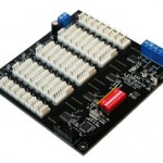
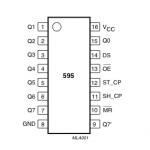
The most commonly used and basic, shift register is the 74HC595. There are lots of tutorials and project using this chip. It has 8 output pins and can be connected in series. After asking a few questions on the Vancouver HackSpace (VHS) mailing list. I was pointed at the 595 Shift Ease - 74HC595 Shift Register Breakout Board. An ingenious little board that lets you combine shift registers together easily to create a long series of shift registers.
I started searching for other shift register that had more output pins and better power management. I found the TLC5947. It has 24x PWM 12bit outputs, better power management, and it has a neat thermal shutdown function (Automatic shutdown at over temperature by that turns off all output drivers). So it if ever gets too hot it turns it self off to protect it. Sounds like the perfect chip, except that it only comes as a surface mount chip (SMT). I never done a SMT before and i have been told that they can be troublesome. One more new skill to learn.
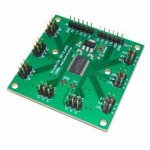
 Now that I found a chip that I can use to operate 192 PWM 12bit output pins I need to build a board for each of these chips. But before stared down the ugly PCB Eagle path, I searched to see what other projects where using that chip. After a little googling I found the OctoBrite DEFILIPPI board. Almost exactly what I was about to make with a few exceptions. The LED connections use a header instead of a 4 pin polarized connectors with common cathode. I can easily work around that but I emailed the manufacture of the board to see if they would make a change to their board for me. Waiting on their responses but even if they can’t make the change I think I will still buy this board.
Next is how to power this project. 192 * ~30 mA = ~5.8 Amps at full brightness (white). Thats a hell of a lot of power and that doesn’t even include the micro-controller (+200 mA) and the motor (~1 Amp). It’s not going to be too much of a problem at MakerFaire where I can connect to the grid but when I am out in the desert at burning man its another story. I will need to power this project off batteries and its going to be troublesome to say the lest. 5.8 Amps is only at full brightness and I will probably code in a brightness limiter so it uses as little power as possible to conserve on battery life and temperature of the chip.
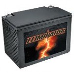
 A 100 Amp/hr deep cycle car battery costs ~$250 CAN and this project could drain it in ~14hrs. So I am going to need at lest two of them and a way of charging them during the day. A ~1000 W solar power set up that is able to charge these batteries is going cost >$2k. A 1000 W generator new is about ~$950 USD to buy but I think I could rent it for a week for a quarter of that, or beg, borrow, or steal it for much less.
Next problem is the micro-controller has to be able to handle a buffer of 810k per sec. A typical Arduino Mega 2560 (thats the big one) has 8k of SRAM. I could use some very tricky programing methods to read the file only as it is needed but even still it would be extremely difficult if not impossible to get it working right. Ideally I would like to have a multi-threaded chip with at lest 4mb of SRAM to buffer as many of the 32k frames between refresh. Still working on this one.
Still lots to think about but at lest some of the parts are coming together.
Item list
- Micro-controller (still researching)
- ~$200, 10x OctoBrite DEFILIPPI boards (2x spare, just incase)
- ~$60, 100x RGB LED, viewing angle ~100, ~9400 MCD @0.59 each
- Physical body (still researching)
- ~$100, Power supply ~10 Amp, 5-12v
I am hoping to spend less then $1000 on this project but i suspect that by the end it will be closer to $1500
RGB LED POV Globe
- RGB LED POV Globe - Research
- RGB LED POV Globe - Research LED
- RGB LED POV Globe - Parts shopping
- RGB LED POV Globe - Research other peoples projects.
- RGB LED POV Globe - Software

Leave a comment