
Raspberry PI and the GPIO pins
This week I have been playing with the Rapberry PI, Python and the Python GPIO pins library.
Software
I started by formatting a SD Card with the Raspbian “ wheezy” (2012-12-16) image from Raspberry PI’s website. I followed this tutorial on how to set up the Raspberry PI for the first time.
I then enabled SSH so I don’t have to attache a monitor, keyboard or mouse to the Raspberry PI. Since my main box is a Windows machine I downloaded and installed PuTTY to use as my SSH client.
Once I was connected to the RPI via SSH, I updated the OS and all of its packages to the latest versions, by running the following command.
sudo apt-get update
Note: This command may take a long time to complete depending on how out of date your system is.
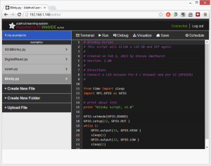
Next I installed the Raspberry Pi WebIDE from adafruit.com. The Web IDE allows you to create Python programs from your webbrowser directly on the Raspberry PI. The WebIDE has a few nice features like a debugger and visualizer and auto version control via bitbucket.
I also installed the “easy_install”, “python-pip“ and “EEML - markup language” and other python packages that I wanted to use.
$ sudo easy_install -U distribute
$ sudo apt-get install python-pip
$ wget -O geekman-python-eeml.tar.gz https://github.com/geekman/python-eeml/tarball/master
$ tar zxvf geekman-python-eeml.tar.gz
$ cd geekman-python-eeml*
$ sudo python setup.py install
Hardware
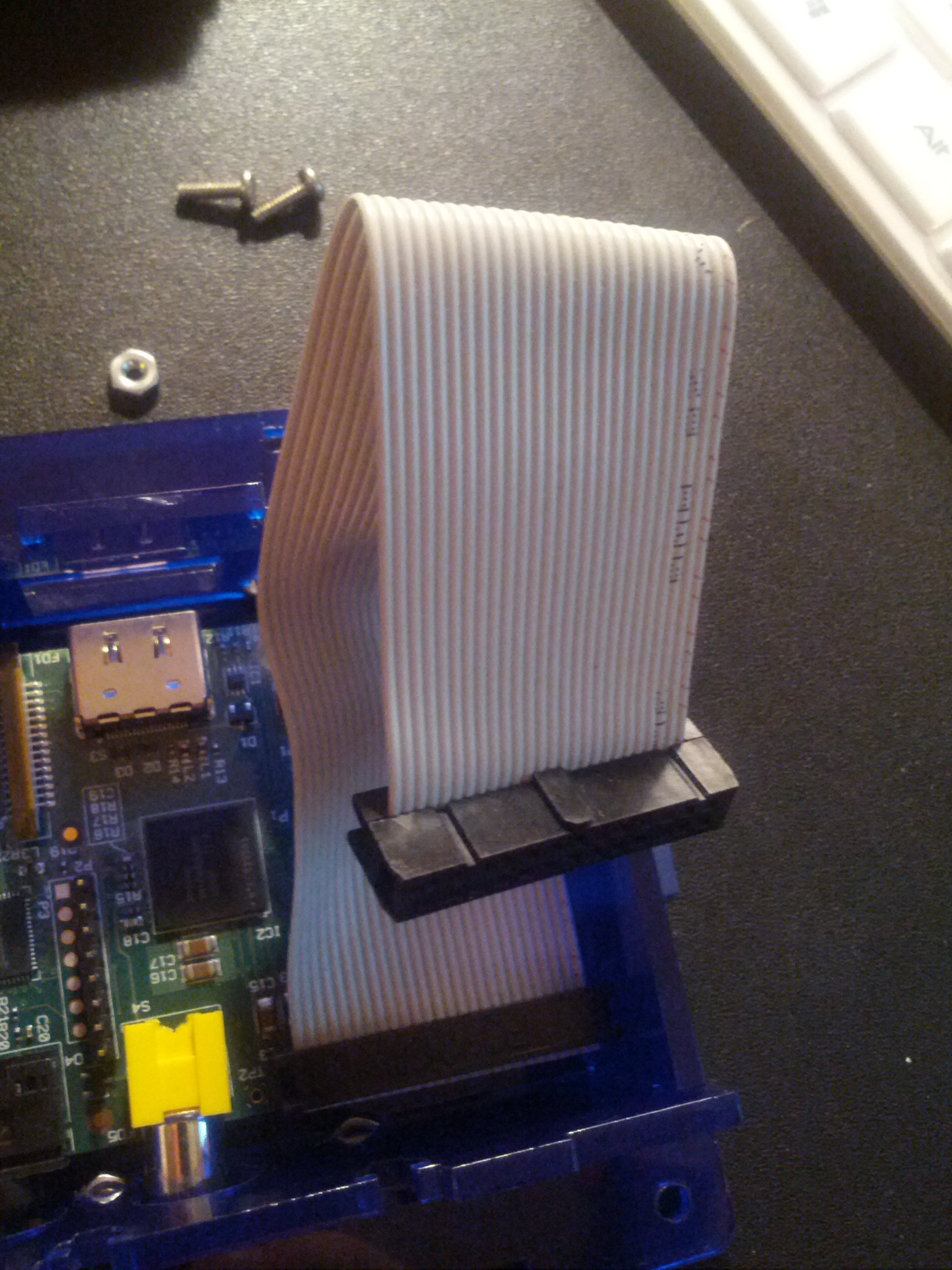 The Raspberry PI has a 26pin mail connector that connects to its GPIO pins. These ribbon cables and breakout boards can be found on adafruit.com ($2.95) and Sparkfun ($2.95)
You can also make your own. Hardware lesson with Gert: make your own ribbon cable connector.
Vancouver Hackspace (VHS) just happen to have a bunch of the 26 pin press connector and I was able to make a few cables.
Source code
Since I am using bitbucket all my source code is public. I created a few learning scripts to understand how the GPIO pins work on the Raspberry PI. The first script I made was a simple blinking LED, just like the arduino blinking LED script. Next was to read the current state of a switch and print the results to the screen.
This image was tremendously helpful in figuring out what pins go where
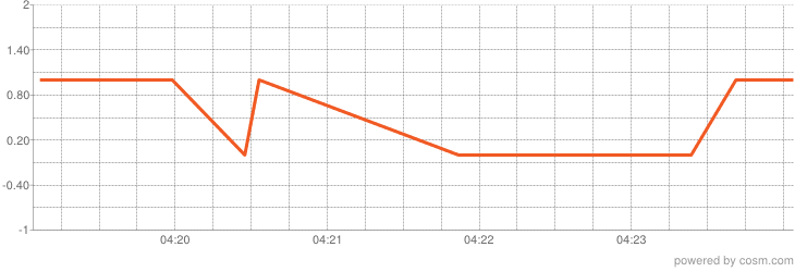
Next I followed Send Raspberry Pi Data to COSM from adafruit.com. I changed the tutorial to read a digital pin (as the Raspberry PI does not have any analog pins) that I connected to a magnetic read switch for my front door.
The GPIO pins on the Raspberry PI are pretty easy to use with the python libary. Its too bad there are no analog pins. I can add AtoD converters or interface the Raspberry PI with an Arduino to add some analog pins.
More to come.
Leave a comment