This post is part of the 100 project ideas project. #The100DayProject. I am looking for feedback. Comment below or DM me via social media Instagram, Twitter.
One Line Pitch
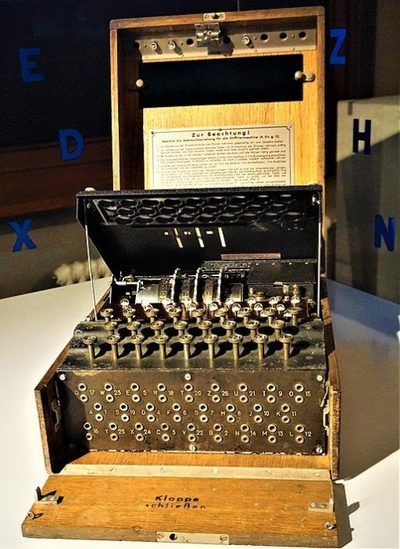
Recreate the German Enigma machine cipher device as a kit using PCBs
Description
 The Enigma machine is a part of computer history. Germany created and used the Enigma machine during World War 2 as a cipher device to create secret messaging for the war effort.
The Enigma has an electromechanical rotor mechanism that scrambles the 26 letters of the alphabet. In typical use, one person enters text on the Enigma's keyboard and another person writes down which of the 26 lights above the keyboard illuminated at each key press. If plain text is entered, the illuminated letters are the ciphertext. Entering ciphertext transforms it back into readable plaintext. The rotor mechanism changes the electrical connections between the keys and the lights with each keypress.
There is a great movie called The Imitation Game (2014) about Alan Turing creating a device (British bombe) that was able to decipher the messages encoded by the Enigma machine.
This video has a good description of how the Enigma machine works. The Enigma Museum has a ton of good information on how it works on a fundamental level. 158,962,555,217,826,360,000 (Enigma Machine) - Numberphile is also great because it goes through the math behind this machine.
I propose creating a kit using several PCBs to illustrate how the Enigma machine works.
The Enigma machine is electro-mechanical using rotors. No processors required. A switch that activates a path for the electricity to illuminate a lamp or LED.
The Enigma machine can be broken down into several different parts.
Keyboard mechanism
A series of 26 switches that correspond to each letter of the alphabet. This could be created with SMT pushbuttons. In a similar fashion to this project 40% club
The output of these keys are 27 pin header. 1 pin for +5v, and 26 pins for alphabet.
Plugboard
26 standard headphone jacks. Using GND and +v for the two wires.
Roters
This is the hardest section to reproduce with PCB boards.
Each router is just test points on a disk shaped PCB. The traces on the routers are set up in the same way that the original Enigma machine was set up. Several different disks.
Between each router, and the reflector and the input box are a disk with pogo pins with springs in them to allow for the electricity to go through each test point, router disk, reflector, and input box. There are SMT based prgo pins.
Rotating the routers is done manually.
There are 5x rotors, Each router has 26 points on it.
Output LEDS
26 LEDs, one LED for each letter of the alphabet.
Prior art
Open Enigma does a very good job on this project and is open source and open hardware. They are using a microcontroller to do the mancail rotations of the routers instead of real disks. KickStarter, and Instructions and good article on the subject Enigma Mark 4. Better than I could make it.
Another project is Enigma-E with less flash or feature then the Open Enigma project
Market
Cryptography nerds, code breakers, world war 2 enthusiasts.