
Idea 004 - Universal Serial breakout board
This post is part of the 100 project ideas project. #The100DayProject. I am looking for feedback. Comment below or DM me via social media Instagram, Twitter.
One Line Pitch
A USB to Serial port board that supports many different physical layers. TTL 3.3v, 5v, RS232, RS485 2wire and 4 wire. DB9, DB25, Screw down terminals, etc
Description
For my work I often need devices to connect to the following types of physical layer devices.
- TTL at 3.3v, TTL at 5v for programing microcontrollers (I rarely if at all do 1.8v)
- RS232 for point to point protocols, Fire Alarm panels, etc..
- RS485 for multi drop protocols like Modbus RTU, BACnet MSTP
- 1-Wire for DS18B20 and other one wire sensors
- 4-20ma current loop for power meters
- Analog 0-10v for lighting controlers
- i2c for Microcontroller devices
- JTAG for Microcontroller debugging
- Dry contact, wet contact, Simple GPIO
In addition to that each of these devices also has their own physical connector.
- DB25 - Old Serial (pre 2000s)
- DB9 - Newer Serial (after 2000)
- 3.5mm audio jack - 5v, GND, data
- T568A - Ethernet (often called RJ45)
- 3-pin JST - WS2812B, NeoPixels
I currently have ~12 dongles and many different connectors and converters on my desk to connect all of these devices to my PC.
It’s ridiculous! We need to develop one universal standard that covers everyone’s use case.

The CH348L supports 8 UARTS exposing the CTS, RTS, DTR pins. It can Mount as a USB Host and shows up in Windows or Linux as 8x serial ports. It also has several GPIO pins that can be used as input or outputs. It would make a good candidate for this project.
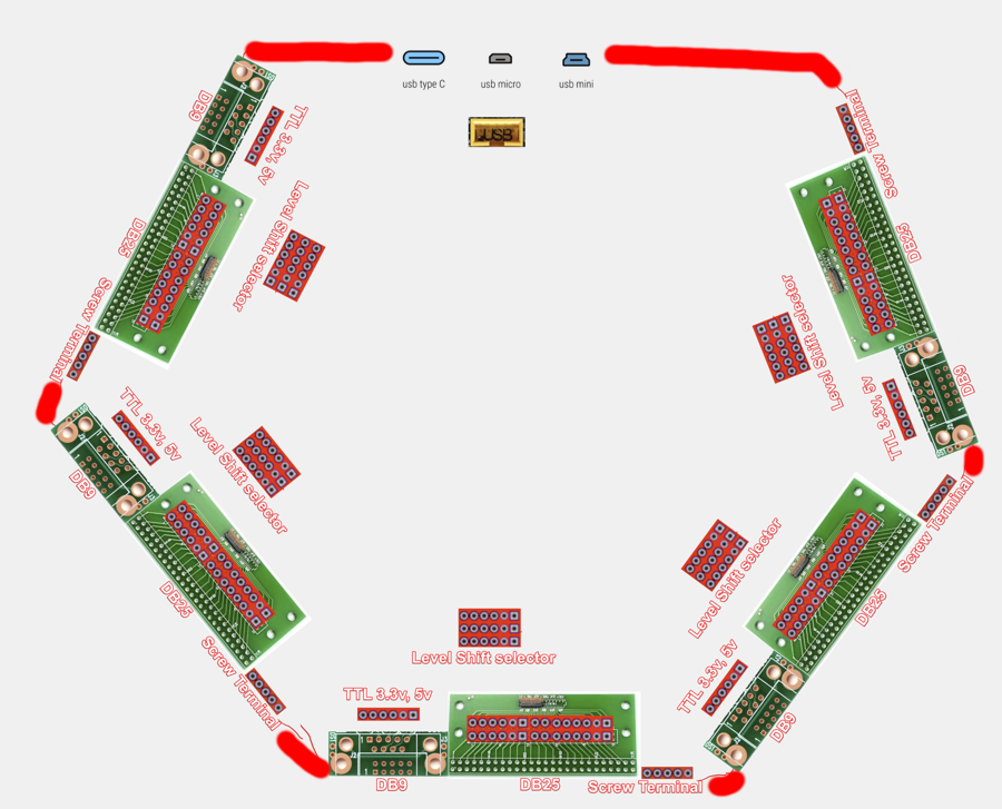
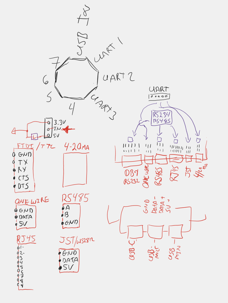
The board would be shaped like a 9 sided polygon. One side for the USB input, and the other 8 sides for each of the UARTs and series of connectors.
All three of the common USB port types could be used in case you have the wrong cable. Not connected at the same time as all the common pins would be connected but would allow for flexibility. USB-C, USB-Mini, USB-Micro. The USB header would also be brought out to a 5x2 header commonly found in ATX motherboards.
Each of the UART sides would have several physical connectors for each UART.
Coming out of the UART a series of jumpers would allow for selection of different level converters. TTL as 3.3v or 5v. Serial as RS232 or RS485, RS485-2W
After the level selector jumpers, on the edge of the board would have several different holes for many different physical connections such as. DB9 Serial, DB25 Serial, RJ45 Ethernet, 9 Pin screw terminal, 2.54 mm (0.1 in) pitch header in two formats (Tom Connector, and FTDI standards). It’s not expected that you would populate each of these physical connector types. Only the ones that you actually need but all the holes would be there if you need them.
The trick is to allow for each of the pins of each of the physical connectors to be brought out to 2.54 mm (0.1 in) pitch header to allow for jumpering using headers if needed.
Side 1, and 5 would be configured in such a way that would allow for a pass through cable. This allows for man in the middle snooping or spying on serial communication. UART 1 connected to the TX, and UART 5 connected to the RX.
Prior art
- Dangerous Prototypes Bus Pirate - A tool for exposing many different formats in a generic way. Its a wonderful tool but missing the hardware connections that I need.
- ACON U- 01 USB TO RS232/RS485 CONVERTER (ISOLATED) - This is what I am currently using, works great for RS232 and RS485 (2wire, 4wire). But is missing the ability to jumper the connectors
- Port to terminal blocks - These work great for wiring unconventional connectors to serial ports.
Market
Hardware hackers, industrial automation, people that work with many different controllers and industrial sensors.
Feedback
- Suggest putting lots of thought into the silk screen. Little things like the arrows I add to TXD and RXD can make the world of difference when the shit is going down and you’re doubting everything.
- Add Diodes to prevent back feeding of the signals and biasing resistors for the RS485 connections. RX and TX LEDs to show status.
- For better compatibility you might want to consider ftdi chips and a USB hub chip to combine them. Better options for leds too.
- Realistically I never needed more then 3x or 4x UARTs at any given time. Then I can make the shape a hexagon.. Because hexagon is the bestagon
- Use DP4T switches like these to select source/destination for uarts.
- The physical connector side of the board could “break off” then you could extend it with some wires from the UART.
- You just separate the level converters onto different pcbs that mate with the base
Leave a comment