RGB LED POV Globe - Status update and mechanical issues
This project has somewhat hit a road block and with 12 days left before Maker Faire I’m starting to panic. This leaves me with ~4 good working days left. Here is my current stats.
Editor and Simulator
At burning man 2010 I saw the Illuminatrix made by Ben Delarre. A RGB LED color grid that was programmable from a JavaScript editor that he made. I was impressed when I saw it at burning man and contacted him early after I started this project to see if I could use his editor for my project. Not only did he let me use the editor but he said that he would change it so it would work specifically with my globe project. A week later and I had my own HBD5000 page on his website with an editor, simulator and a few example animations. Amazing Ben Delarre is awesome.
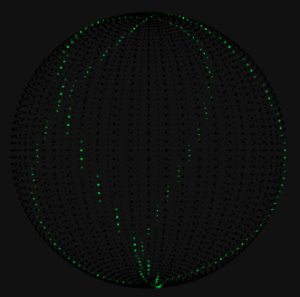
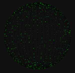
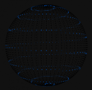
Example animations: Click the images to see a simulation.
Please generate your own animations with the editor. We need more animations!
Software
Software is basically done, I’m still having problems steaming frames at full speed over bluetooth, but half frame rate is works great. On the Arduino Mega I can buffer ~19 full color frames and the Arduino uno I can buffer ~10 full frames. As I am displaying the frames to the users I can stream in new frames over bluetooth. The whole system works pretty well and with so little time left I probably won’t be changing it anytime soon.
The Mechanical
The first wheel I made was a 6 foot monstrosity of bent tube stock. While I was doing my testing it was a little unbalanced and bent under the stress. As soon as it bent even a little the problem got exasperated and by the time I was able to shut it down the whole ring was bent out of shape and unrecoverable. It was an expensive and time consuming mistake. Luckily I was not running it at full speed or it could have sheared off its hinge and hurt someone as it flew though the air.
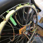
At this point I decided to shrink my project down from a 6 foot tall ring to the biggest bicycle rim that I could find. The bicycle rim is already sturdy enforced with the spokes, light and balanced. The project is smaller but much safer.
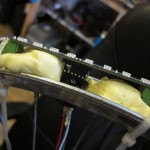
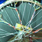
I drilled some holes in the rim for wires to run though and buffered the LEDs with expanding foam. Its not pretty but it works surprisingly well.
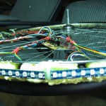
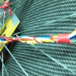
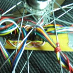
Next I secured the Led boards, wires and the controller boards to the spokes of the bicycle rim. These components will be spinning at great speeds so I took extra care to make sure that they won’t be going anywhere.
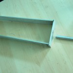
Next I attached the bolts to a tuning fork like mount that Arthur Hazleden a fellow Vancouver Hackspace member made for me.
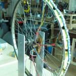
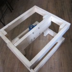
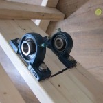
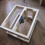
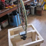
Next I made a box out of wood with two pillows bolted to a center brace. A pillow is ball baring mount that should let the center shaft spin freely while saying in position.
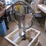
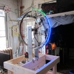
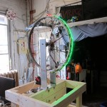
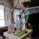
In this video/pictures you can see the LEDs lit up. I used a C Camp to keep the wheel from falling over. Ignore the voices in the background they are from the scary ally behind Vancouver Hackspace.
Power
I used a standard computer power supply to power all the LEDs and electronics on the wheel. This works really well and I suggest it for anyone that is powering large amounts of LEDs. The power supply comes with both 5v and 3.3v rails. A common computer power supply also filters and smooths out the current before passing it on to the LEDs.
There is a simple trick for turning on a PC’s power supply without a PC. Basically you need to short the green {PS_ON} pin with any of the black wires {COM} on the power supply.
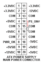
I am using a 3 connection slip ring to transfer power from the stationary base and power supply to the rotating wheel. There are lots of industrial slip rings available online but they are pretty expensive. You can make your own slip ring but with something so important to this project I decided to buy one.
Safety at Maker Faire
Because of my previous mishap with the larger ring, and because the ring is spinning so fast the good people at Vancouver mini Maker Faire had valid concerns about the safety of this project. The code name of this project probably didn’t help much either. HBD5000 = Hippy Ball of Death 5000.
I decided to encase the spinning parts of my project with Polyethylene terephthalate aka PET-G or better known as the stuff that pop bottles are made from. Its has a few good properties that plexi glass doesn’t. Its easy to mode in to shape, it bends and warps instead of shattering, and most importantly its cheap.
They also connected me with Farrell Segall who has successfully created a few different POV projects that he plans to bring to Vancouver Maker faire this year. We met up at the Vancouver Hackspace and he showed me his impressive POV projects as well as some other very interesting projects that he is working on. He suggested that I make a mount at the top of the POV with a pillow so that the Ring won’t be able to wobble too much. Great idea!
With the top mount and the PET-G even if this project does spin honorably out of control it shouldn’t hurt anyone.
Issues
- The bluetooh receiver broke while I was mounting it to the Arduino board. Ordered another one and it should be here 2 days before Maker Faire. If it does not get here in time I will pre program the POV with a single image and use that to demo it.
- I have no welding skills and i'm reliant on others to do the welds that I need for this project.
- I have burnt out two used motors testing this project. I have purchased a bran new motor for Maker faire but if it burns out on site I will not be able to replace it.
- Spinning speed, there is a controversy on what speed I should spin the ring at. Its safer at slower speeds but I will get less frame rate. The POV is not spinning yet so I can not test it at different speeds.
Whats left to do
- Add the top mount for safety
- Add the PET-G container for safety
- Get it spinning
- Mount the power supply
- Add the slip ring to transfer power to the wheel.

Leave a comment